
产品应用
Sinuofuhong
此文档将提供应用开发使用电容器(EDLC)基本使用指南。若在开发使用过程中遇到问题且在此文件中找不到解决答案时请与我们联系。
This document provides basic guidelines for application development using capacitors, also known as EDLC. If questions arise during your development process and are not answered in this document, please contact us.
寿命Life Time
EDLC具有比二次电池更长久的寿命,其寿命可达数十万次以上。EDLC基本的寿命终止失效模式为等效串联电阻(ESR)升高和/或容量的降低。实际的寿命终止标准取决于应用要求。长期置于高温下,高电压和超电流将会导致ESR升高和容量降低。这些参数的降低将可延长超级电容器的寿命。一般来说,圆筒型EDLC具有与电解电容器相类似的构造,有电解液、铝壳和胶粒。多年使用后,EDLC内电解液也会干涸,如同电解电容器一样,导致ESR升高,寿命终止。
EDLC has a longer life time than secondary batteries, Their cycle life can reach hundreds of thousands of times. The basic end-of-life failure mode for an EDLC is an increase in equivalent series resistance (ESR) and/or a decrease in capacitance. The actual end-of-life criteria are dependent on the application requirements. Prolonged exposure to elevated temperatures, high applied voltage and excessive current will lead to increased ESR and decreased capacitance. Reducing these parameters will lengthen the life time of a supercapacitor. In general, cylindrical EDLC have a similar construction to electrolytic capacitors, having a liquid electrolyte inside an aluminum can sealed with a rubber bung. Over many years, the EDLC will dry out, similar to an electrolytic capacitor, causing high ESR and eventually end-of-life.
电压Voltage
EDLC是有额定的工作电压的。电压值是基于其最高额定温度下最长寿命来设定的。如果使用电压超出了推荐电压,其结果将会导致寿命缩短。如果电压长期过高,EDLC内将会产生气体,导致漏液或防爆阀破裂。EDLC是可以承受短期过电压的。
EDLC are rated with a nominal recommended working or applied voltage. The values provided are set for long life at their maximum rated temperature. If the applied voltage exceeds this recommended voltage, the result will be reduced life time. If the voltage is excessive for a prolonged time period, gas generation will occur inside the EDLC and may result in leakage or rupture of the safety vent. Short-term over voltage can usually be tolerated by the EDLC.
极性Polarity
EDLC的设计是有相对称的电极,即两极具有相类似的成分。在EDLC初次组装时,任一电极都可定为正极或负极。一旦EDLC在100%质量测试时第一次充电,其电极将会形成极性化。每-EDLC都有负极框或符号来标识极性。尽管其可以降低到零电压,其电极还是会保留非常少的电荷。虽然之前充电的EDLC会放电至-2.5V且在容量或ESR方面至极低,但还是不能进行反极使用。
EDLC are designed with symmetrical electrodes, meaning they are similar in composition. When an EDLC is first assembled, either electrode can be designated positive or negative. Once the EDLC is charged for the first time during the 100% QA testing operation, the electrodes become polarized. Every EDLC either has a negative stripe or sign denoting polarity. Although they can be shorted to zero volts, the electrodes maintain a very small amount of charge. Reversing polarity is not recommended, however previously charged EDLC have been discharged to -2.5V with no measurable difference in capacitance or ESR.
注:在一方向上保留的电荷越久,EDLC就越变的极性化。如果在一方向上长期充电后再进行反向充电,EDLC的寿命将会大大的缩减。
Note:The longer they are held charged in one direction,the more polarized they become.If reversely charged after prolonged chargeing in one direction,the life of the EDLC may be shortened.
温度Ambient Temperature
SEE系列电容的标准温度范围为-25℃~70℃。SEL系列电容的标准温度范围为-40℃~60℃。温度及电压会对EDLC寿命有影响。一般来说,环境温度每提升10℃,EDLC寿命就会缩短一半。因此,建议尽可能在规定温度范围内使用EDLC以降低内部劣化与ESR升高。在低于正常室温环境下,可使用稍高于额定工作电压而不造成内部劣化和寿命缩短。在低温下提升使用电压将可抵销ESR的升高。高温下ESR的升高会导致EDLC永久性劣化/电解液分解。在低温下,因电解液粘性的提升及离子的缓性移动缘故,ESR升高只是一种短暂现象。
The standard temperature rating is -25℃ to 70℃ for SEE series or -40℃ to 60℃ for SEL series. Temperature in combination with voltage can affect the life time of an EDLC. In general, raising the ambient temperature by 10℃ will decrease the life time of an EDLC by a factor of two. As a result, it is recommended to use the EDLC at the Specified temperature range possible to decrease internal degradation and ESR increase. At temperature lower than normal room temperature, it is possible to apply voltages slightly higher than the recommended working voltage without significant increase in degradation and reduction in life time. Raising the applied voltage at low temperatures can be useful to offset the increased ESR seen at low temperatures. Increased ESR at higher temperatures is a result of permanent degradation/electrolyte decomposition inside the EDLC. At low temperatures, however, increased ESR is only a temporary phenomenon due to the increased viscosity of the electrolyte and slower movement of the ions.
放电特性Discharge Characteristics
EDLC放电时电压是呈斜线的。在确定应用时的容量与ESR要求时,考虑耐压放电和电容性放电成分是很重要的。在高脉冲电流应用时,内阻值是最为关键的。在低电流长时间应用时,电容放电特性是最为关键的。
EDLC discharges with a sloping voltage curve. When determining the capacitance and ESR requirements for an application, it is important to consider both the resistive and capacitive discharge components. In high current pulse applications, the resistive component is the most critical. In low current, long duration applications, the capacitive discharge component is the most critical.
在I电流下放电t(秒)时电压降低Vdrop公式为:
Vdrop = I(R+t/C)
The formula for the voltage drop, Vdrop, during a discharge at I current for t seconds is:
Vdrop = I(R+t/C)
在脉冲电池应用时,须使用低ESR(R值)EDLC以减低电压降幅。
To minimize voltage drop in a pulse application, use an EDLC with low ESR(R value).
在低电流应用时,应使用高容量(C值)EDLC。
To minimize voltage drop in a low current application, use an EDLC with large capacitance(C value).
充电方法Charge Methods
EDLC可用各种方法进行充电,包括恒定电流、恒定功率、恒定电压或与能量储存器,如电池、燃料电池、直流转换器等进行并联。如果EDLC与电池并联,加一个低阻值串联电阻将会提升电池的寿命。如果使用串联电阻,须确保EDLC输出电压输出端是直接与应用器连接而不是通过电阻与应用器连接,否则EDLC的低ESR将无效。在高脉冲电流放电时,许多电池系统寿命缩短均会缩短。
.png)
EDLC can be charged using various methods including constant current, constant power,constant voltage or by paralleling to an energy source, i.e. battery, fuel cell, DC converter, etc. If an EDLC is configured in parallel with a battery, adding a low value resistor in series will increase the life of the battery. If a series resistor is used, ensure that the voltage outputs of the EDLC are connected directly to the application and not through the resistor; otherwise the low ESR of the EDLC will be nullified. Many battery systems exhibitdecreased life time when exposed to high current discharge pulses.
EDLC最大建议充电电流I应按以下方式计算,Vw为充电电压,R为EDLC ESR:
I= Vw/5R
The maximum recommended charge current l, for an EDLC where Vw is the charge voltage and R is the EDLC ESR is calculated as below:
I = Vw/5R
持续大电流或高电压充电,EDLC将会过度发热。
过度发热将会导致ESR提升,气体产生,寿命缩短,漏液,防爆阀破裂。
如果要使用高于额定值的电流或电压充电请与生产厂商联系。
Overheating of the EDLC can occur from continuous over current or overvoltage charging.
Overheating can lead to increased ESR, gas generation, decreased life time, leakage, venting or rupture.
Contact the factory if you plan to use a charge current or voltage higher than specified.
自放电与漏电流Self Discharge and Leakage Current
以不同方法进行测量时自放电和漏电流在本质上是相同的,因为EDLC在构造上,从正极到负极具备高的耐电流特性。也就是说为保留电容电荷,是需要少量的额外电流,此称为漏电流。当充电电压移除,电容不在负荷时,额外的电流会促使EDLC放电,此称为自放电电流。
Self discharge and leakage current are essentially the same thing measured in different ways. Due to the EDLC construction, there is a high-resistance internal current path from the anode to the cathode. This means that in order to maintain the charge on the capacitor a small amount of additional current is required. During charging this is referred to as leakage current. When the charging voltage is removed, and the capacitor is not loaded, this additional current will discharge the EDLC and is referred to as the self discharge current.
为测量实际的漏电流或自放电数值,也因为构造原因,EDLC须充电100小时以上。EDLC可模拟为几个并联的电容器,每一个都有不同的串联电阻值。低串联电阻值的电容器能迅速充电从而提升终端电压达到充电电压值的同一水平。但在充电电压移除时,如果这些并联的电容器之中有未完全充电的话,电容器将会放电到具有较高串联电阻的并联电容器中。结果就是终端电压将会降低,形成高自放电电流。须注意容量越高,完全充电时间就越久。
In order to get a realistic measurement of leakage or self discharge current the EDLC must be charge for in excess of 100 hours. This again is due to the capacitor construction. The EDLC can be modeled as several capacitors connected in parallel, each with an increasing value of series resistance. The capacitor with low values of series resistance is charged quickly thus increasing the terminal voltage to the same level as the charge voltage. However, if the charge voltage is removed these capacitors will discharge into the parallel capacitors with higher series resistance if they are not fully charged. The result of this is that the terminal voltage will fall, giving the impression of high self discharge current. It should be noted that the higher the capacitance value, the longer it will take for the device to be fully charged.
EDLC系列设置Series Configurations of EDLC
单个SEE系列EDLC电压限制为2.5V,SEL系列EDLC电压限制为2.7V。因许多应用领域要求高电压.EDLC可以设置为串联以提升工作电压。确保单一的EDLC电压不超过其最大的额定工作电压是很重要的,否则会导致电解液分解,气体产生,ESR升高,寿命缩短。
Individual EDLC is limited to 2.5V for SEE series or 2.7V for SEL series. As many applications require higher voltages, EDLC can be configured in series to increase the working voltage. It is important to ensure that the individual voltage of any single EDLC does not exceed its maximum recommended working voltage as this could result in electrolyte decomposition, gas generation, ESR increase and reduced life time.
予充电和放电时,在稳态下因容量差异和漏电流差异,电容器电压不平衡现象将会产生。在充电时,串联电容器将起到电压分配作用,因此高容值单体将会承受更大的电压。例如:2个1F电容器进行串联,一个电容器容量为+20%,另一个容量为-20%,电压通过电容器的最差性况为:
Vcap2= Vsupply x (Ccapl/(Ccapl+Ccap2))
其中Ccapl具备+20%容量,则 Vsupply= 5V。
Vcap2= 5V x (1.2/(1.2+0.8))=3V
Capacitor voltage imbalance is caused, during charge and discharge, by differences in capacitance value and, in steady state, by differences in capacitor leakage current. During charging series connected capacitors will act as a voltage divider so higher capacitance devices will receive greater voltage stress. For example if two 1F capacitors are connected in series, one at +20% of nominal capacitance the other at -20% the worst-case voltage across the capacitors is given by:
Vcap2 = Vsupply x (Ccapl/(Ccapl+Ccap2))
where Ccapl has the +20% capacitance. So for a Vsupply = 5V.
Vcap2 = 5V x (1.2/(1.2+0.8)) = 3V
从上可以看出,为避免超出3V的EDLC浪涌电压范围,串联电容器的容值应在±20%的公差范围内。在选择上,一个合适的主动电压平衡电路可用来降低因容值不平衡而产生的电压不平衡。需注意到大多数的电压平衡方法都取决于具体的应用。
From this it can be seen that, in order to avoid exceeding the EDLC surge voltage rating of 3V, the capacitance values of series connected parts must fall in a +20% tolerance range. Alternatively a suitable active voltage balancing circuit can be employed to reduce voltage imbalance due to capacitance mismatch. It should be noted that the most appropriate method of voltage balancing will be application specific.
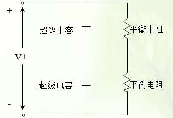
被动电压平衡Passive Voltage Balancing
被动电压平衡可用电压分配电阻与每一EDLC并联来实现。这可让电流从高电压的EDLC上流至低电压的EDLC上从而实现电压的平衡。最重要是选择平衡电阻值以提供EDLC更高电流的流动而不增加 EDLC的漏电流。须记住在高温下漏电流是会上升的。
Passive voltage balancing uses voltage-dividing resistors in parallel with each EDLC. This allows current to flow around the EDLC at a higher voltage level into the EDLC at a lower voltage level, thus balancing the voltage. It is important to choose balancing resistor values that provide for higher current flow than the anticipated leakage current of the EDLC, bearing in mind that the leakage current will increase at higher temperatures.
被动电压平衡只在不经常进行EDLC充放电使用和使用能承受平衡电阻的额外电流负载时推荐使用。建议所选择的平衡电阻应能提供最差EDLC漏电流50倍以上的额外电流(根据最高使用温度选择3.3 KΩ~22kΩ的电阻)。尽管更大阻值的平衡电阻在大多数情况下也能工作,但其不可能在不匹配的电容器串联时起到保护作用。
Passive voltage balancing is only recommended for applications that don't regularly charge and discharge the EDLC and that can tolerate the additional load current of the balancing resistors. It is suggested that the balancing resistors be selected to give additional current flow of at least 50 times the worst-case EDLC leakage current (3.3kΩ t0 22kΩ depending on maximum operating temperature). Although higher values of balancing resistor will work in most cases they are unlikely to provide adequate protection when significantly mismatched parts are connected in series.
主动电压平衡Active Voltage Balancing
主动电压平衡电路能使串联的EDLC上的电压与额定电压驱同而不管有多少电压不平衡产生。同时确保在稳态情况下准确的电压平衡电路能有效地降低电流,而且只在电容电压发生不平衡时才要求更大的电流。这些特性使得主动电压平衡电路是EDLC频繁充放电及如电池等能量组件使用的最理想电路。
Active voltage balancing circuits force the voltage at the nodes of series connected EDLC to be the same as a fixed reference voltage, regardless of how any voltage imbalance occurs. To ensure accurate voltage balancing, active circuits typically draw much lower levels of current in steady state and only require larger currents when the capacitor voltage goes out of balancing. These characteristics make active voltage balancing circuits ideal for applications that charge and discharge the EDLC frequently as well as those with a finite energy source such as a battery.
反极性保护Reverse Voltage Protection
当串联EDLC迅速放电,容量值低的电容器之上的电压将潜在地变为负电压。如之前的解释,此是不希望出现的且会缩短EDLC的工作寿命。一种简单的防护逆向电压的方法是在电容器上增加一个二极管。使用适当的额定的限流二极管替代标准的二极管,还可以保护EDLC出现过电压现象。需要谨慎的是确保二极管能承受电源的峰值电流。
When series connected EDLC are rapidly discharged, the voltage on low capacitance value parts can potentially go negative. As explained previously, this is not desirable and can reduce the operating life of the EDLC. One simple way of protecting against reverse voltage is to add a diode across the capacitor,configured so that it is normally reverse bias. By using a suitably rated zener diode in place of a standar diode the EDLC can also be protected against overvoltage events. Care must be taken to ensure that the diode can withstand the available peak current from the power source.
焊接信息 Soldering Information
过热会导致EDLC电性能的退化,漏液或内压升高。焊接应遵循以下具体指示:
Excessive heat may cause deterioration of the electrical characteristics of the EDLC, electrolyte leakage or an increase in internal pressure. Follow the specific instructions listed below:
另外:
1.不要把EDLC浸入已熔解的焊锡中。
2.只在EDLC导针上粘上焊剂。
3.确保EDLC套管不直接与PCB或其它组件接触。过高的焊锡温度会导致套管收缩或破裂。
4.避免EDLC在裸露的电路板之下工作以防止短路发生。
In addition
1.Do not dip EDLC body into melted solder.
2.Only flux the leads of the EDLC.
3.Ensure that there is no direct contact between the sleeve of the EDLC and the PC board or any other component. Excessive solder temperature may cause sleeve to shrink or crack.
4.Avoid exposed circuit board runs under the EDLC to prevent electrical shorts.
手工焊接Manual Soldering
不可让EDLC外部套管与焊棒接触,否则套管会熔化或破裂。焊嘴温度建议低于350℃,焊接持续时间少于4秒钟。应使烙铁与EDLC导针直接接触时间最小化,因为导针过热会提高等效串联电阻值(ESR)。
Do not touch the EDLC's external sleeve with the soldering rod or the sleeve will melt or crack. The recommended temperature of the soldering rod tip is less than 350℃ and the soldering duration should be less than 4 seconds. Minimize the time that the soldering iron is in direct contact with the terminals of the EDLC as excessive heating of the leads may lead to higher equivalent series resistance (ESR).
波峰焊Wave Soldering
最多给PCB预热60秒钟,浸锡达0.8mm或更厚。预热温度极限应低于100℃。
Use a maximum preheating time of 60 seconds for PC boards 0.8mm or thicker. Preheating temperature should be limited to less than 100℃.
以下表格信息只用于导针的波峰焊接:
Use the following table for wave soldering on leads only:
|
焊锡温度(℃) |
建议焊锡时间 |
最大焊接时间 |
|
220℃ |
7 |
9 |
|
240℃ |
7 |
9 |
|
250℃ |
5 |
7 |
|
260℃ |
3 |
5 |
回流焊接Reflow Soldering
除非EDLC有明确的额定耐回流焊接温度,否则不应对EDLC使用回流焊接而应使用红外线或传送烤炉加热方法进行焊接。
Do not use reflow soldering on EDLC using infrared or convection oven heating methods unless the EDLC is specifically rated to withstand reflow soldering temperature.
纹波电流Ripple Current
尽管EDLC相对于其它超级电容来说有很低的电阻,其还有比铝电解电容器更高的电阻且在纹波电流之中容易受内部热量的影响而使ESR升高,寿命缩短。为确保长久的寿命,推荐的最大纹波电流不应使EDLC表面温度提升高于3℃。
Although EDLC have very low resistance in comparison to other supercapacitors, they do have higher resistance than aluminum electrolytic capacitors and are more susceptible to internal heat generation when exposed to ripple current. Heat generation leads to electrolyte decomposition, gas generation, increased ESR and reduced life time. In order to ensure long life time, the maximum ripple current recommended should not increase the surface temperature of the EDLC by more than 3℃.
电路板设计Circuit Board Design
尽量避免清洁电路板,如果要进行电路板清洁,应使用标准电路板清洁液通过无静电或超音波浸渍方法进行清洁,时间不超过5分钟,最高温度不高于60℃。之后要彻底冲洗和风干。一般来说,应将EDLC如同铝电解电容器一样对待。
Avoid cleaning of circuit boards, however if the circuit board must be cleaned use static or ultrasonic immersion in a standard circuit board cleaning fluid for no more than 5 minutes and a maximum temperature of 60℃. Afterwards thoroughly rinse and dry the circuit boards. In general, treat EDLC in the same manner you would an aluminum electrolytic capacitor.
长期贮存Long Term Storage
不要在以下环境中贮存EDLC:
1.局温/高湿度下贮存
2.直接与腐蚀性材料、酸、碱金属或有毒气体接触
3.阳光直射
4.粉尘环境
5.冲击和/或振动环境
Do not store EDLC in any of the following environments:
1.High temperature and/or high humidity
2.Direct contact with corrosive materials, acids, alkalis or toxic gases
3.Direct exposure to sunlight
4.Dusty environment
5.Environment subject to excessive shock and/or vibration
运输信息Transportation Information
EDLC未受到US DOT(运输部)和IATA的规定。正确的国际运输描述是“电子产品-电容器”。
EDLC are non-regulated by the US DOT (Department of Transport) and IATA. The correct international shipping description is “Electronic Parts – Capacitors”.
应急程序 Emergency Procedures
如果发现EDLC过热或是闻到香的气味,应立即断开与EDLC连接的电源或负载。让EDLC降温,然后进行正确处理。不可让脸或手接触过热的EDLC。如果EDLC发生漏液或防爆阀破裂请与生产厂商联系索取材料安全资料表。
If an EDLC is found to be overheating or if you smell a sweet odor, immediately disconnect any power or load to the EDLC. Allow the EDLC to cool down, then dispose of properly. Do not expose your face or hands to an overheating EDLC. Contact the factory for a Material Safety Date Sheet if an EDLC leaks or vents.
如果有漏液情况:
皮肤接触:用肥皂和水冲洗皮肤。
眼睛接触:用水清洗眼睛15分钟,看医生。
吸取:喝牛奶/水并吐出,看医生。
If exposed to electrolyte:
Skin Contact: Wash exposed area thoroughly with soap and water.
Eye Contact: Rinse eyes with water for 15 minutes and seek medical attention.
ngestion: Drink milk/water and induce vomiting; seek medical attention.
一般性安全考虑General Safety Considerations
如果过度充电,反向充电,焚烧或高于150℃加热,EDLC有可能发生防爆阀爆裂。不要压挤,损伤,压钉或拆解EDLC。滥用EDLC可能导致铝壳上高温(烧伤)。
EDLC may vent or rupture if overcharged, reverse charged, incinerated or heated above 150℃. Do not crush, mutilate, nail penetrate or disassemble. High case temperature (burn hazard) may result from abuse of EDLC.
废弃处理程序。
Disposal Procedures.
不要随便丢弃。应根据当地法律法规进行处理。
Do not dispose of unit in trash. Dispose of according to local regulations
温度表现 Thermal Performance
使用时能量贮存单位上低内阻会使得低热量产生。电子产品使用温度越低,其工作时间越久。大多数使用领域自然空气对流都能提供足够的冷却环境。在恶劣环境中使用,还要求有最长的使用寿命则需要添加一些空气对流设备。
Low internal resistance of the energy storage units enables low heat generation within the units during use. As with any electronic components the cooler the part operates the longer the service life. In most applications natural air convection should provide adequate cooling. In severe application requiring maximum service life some forced airflow may be required.
针对耐热来说,测量产品的Rth需在环境温度(-25℃)下进行并允许自然对流。数据表上的Rth值对确定产品工作极限值是有用的。利用Rth值,可计算出任何电流和工作循环下的温升。
The thermal resistance, Rth of the units has been experimentally determined assuming free convection at ambient (-25℃). The Rth value provided on the data sheet is useful for determining the operating limits for the units. Using the Rth value a module temperature rise can be determined based upon any current and duty cycle.
温度升高值可按以下等式算出:
△T = Dc*Rth*I2*Resr
其中:Dc=工作循环
I=AC/DC电流
Rth=耐热性(℃/W)
Resr=等效串联电阻,(Ohms)(使用直流电)
The temperature rise can be expressed by the following equation:
△T = De*Rth*I2*Resr
Where:Dc=Duty Cycle
I=Current AC/DC(A)
Rth=Thermal Resistance(℃/W)
Resr=Equivalent Series Resistance,(Ohms)(DC value used)
特性Features:
1.可用作充电电池及后备电源。
2.具备数十万次充电/放电循环次数,免却废物处理。
3.不含有毒材料,如镍及镉。
1.Can be used as a rechargeable battery and ideal for backing up purpose.
2.Capable of several hundreds of thousands of charge/discharge cycles; free from throwaway disposal.
3.Does not contain toxic materials such as nickel and cadmium.
【Last : 车辆低温启动 】 【[ Back ]】 【 Next : 混合动力汽车】